7.8 DESIGN OF PROPELLANT VALVES
Propellant valves are used to initiate and terminate propellant flows to main thrust chambers and gas generators. They are usually openclosed, two-position, normally-closed valves. To meet specific sequencing requirements, other designs may provide for an intermediate opening position. For thrust-throttle or mixture-ratio- control purposes, ability for continuously variable opening position may be required.
In addition to propellant compatibility and structural integrity, prime design considerations for propellant valves are: (1) No leakage of propellant through the valve when closed (2) Proper actuating time during opening and closing in accordance with the requirements of the control system (3) Minimum pressure drop
A great variety of propellant valve types is available. Each design has certain characteristics which make it suitable for a specific application. Frequently used propellant valves, classified according to their design configurations, are: (1) Butterfly valves (2) Ball valves (3) Poppet valves (4) Venturi valves (5) Gate valves (6) Needle valves
Butterfly-Type Propellant Valves
The butterfly valve is one of the most widely used propellant valve types in large liquid propellant rocket engines. It has established a reliable operational record in , storable, and other liquid propellant services. Existing butterfly valve designs range from 2 to 17 inches nominal diameter, for use at propellant pressures from 20 to over 1500 psia . With improvements in sealing and structural details, successful designs for higher capacities and propellant pressures are certain to be achieved.
Figure 7-33 presents a typical butterfly valve design. Sealing is provided by a lip seal, which engages a spherical surface on the valve gate, similar to figure 7-28. The valve gate pivots on the valve shaft, the axis of which passes through the geometric center of the spherical sealing surface. In most designs, the valve gate rotates from the closed to the fully opened position. The valve is operated by a piston-type actuator, through a connecting link and shaft crank arm. Lip seals are used as dynamic seals for the rotating valve shaft (fig. ). The actuating power is furnished either by noncryogenic propellant pressure, or by an inert gas supply, and
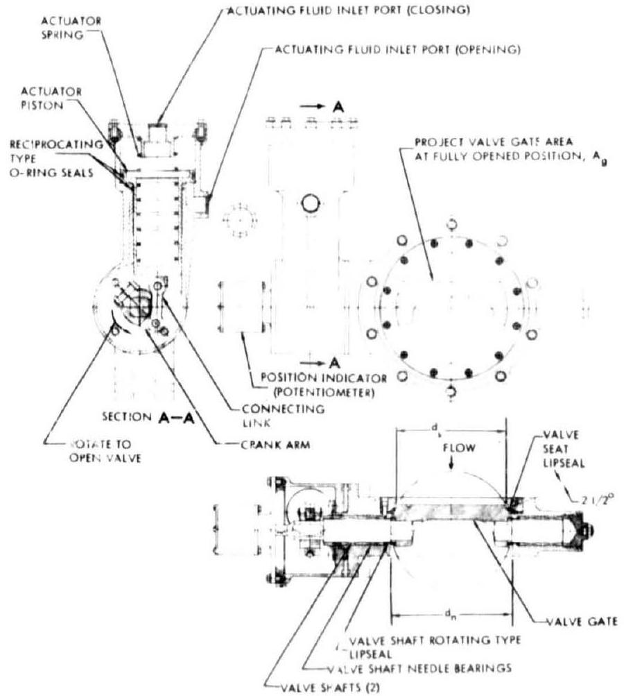 Figure 1-33.-Typical dutterfly-type propellant valve design (shown in the closed position).
controlled by a pilot valve. The valve shown is designed to be normally closed by a spring which is installed on the closing side of the actuator piston. Except for shaft and pins which are made of stainless steels, most of the other parts are made of aluminum-alloy forgings. Figure 7-34 shows a 4 -inch, butterfly-type, liquid oxygen valve used on the Rocketdyne Atlas ICBM booster engine.
Butterfly valves have relatively low resistance to fluid flow. They are compact, light, and easy to service. They have a high characteristic area which can be expressed as
where (see fig. 7-33 for dimension references) characteristic area of the valve, in inside diameter of the valve seat lip seal, in projected valve gate area at the fully open position, in Values for range from 65 percent of the duct area (duct area , where valve nominal diameter, in) on a 2 -inch size valve, to about 87 percent of the duct area on a 12 -inch
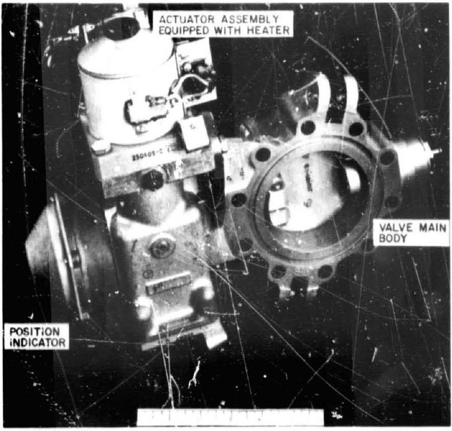 Figure 7-34.-Four-inch butterfly-type main liquid oxygen valve used on Rocketdyne Atlas ICBM booster engines.
valve. A butterfly valve maintains a relatively smooth fluid-flow stream over a wide range of valve-gate angular positions. Thus, when used as a throttle valve, it has little tendency toward turbulence with attendant adverse effects such as local propellant cavitation. Typical fluidflow resistance coefficients at various opening positions of a butterfly valve are listed in table 7-4.
When RP-1 is used as the actuating fluid for the liquid oxygen valve, in a system such as the A-1 stage engine, a heater may be required at the actuator to keep the RP-1 from freezing. The actuator-valve arrangement of the butterfly valve shown in figure 7-33 provides flexibility for specific engine control system needs: the valve may be normally open or normally closed; position indicators may be added; closing of the valve may be accomplished by means of a pyrotechnic squib, rather than by pneumatic pressure. Figure 7-35 illustrates the linkage between the main oxidizer valve and the igniter fuel sequence valve of the A-1 stage engine. During the opening stroke, the cam attached to the main oxidizer valve shaft actuates the igniter fuel sequence valve to open. Frequently, a potentiometer is also attached to the shaft for continuous indication of the angular position of the valve gate.
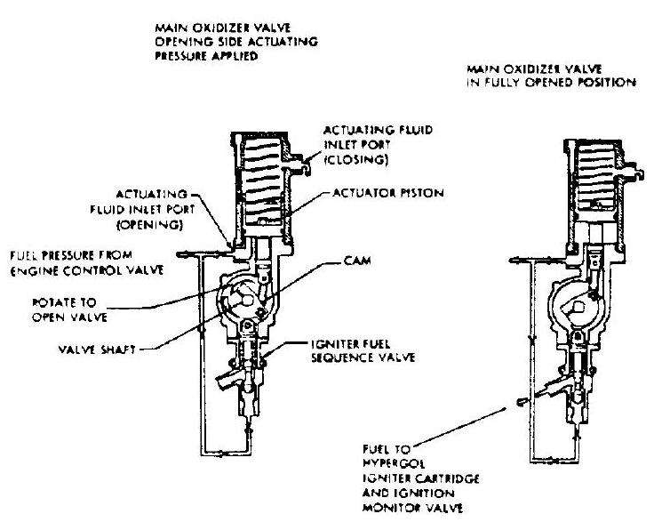 Figure 7-35.-Mechanically linked arrangement between the main oxidizer valve and the igniter fuel sequence valve of the A-1 stage engine.
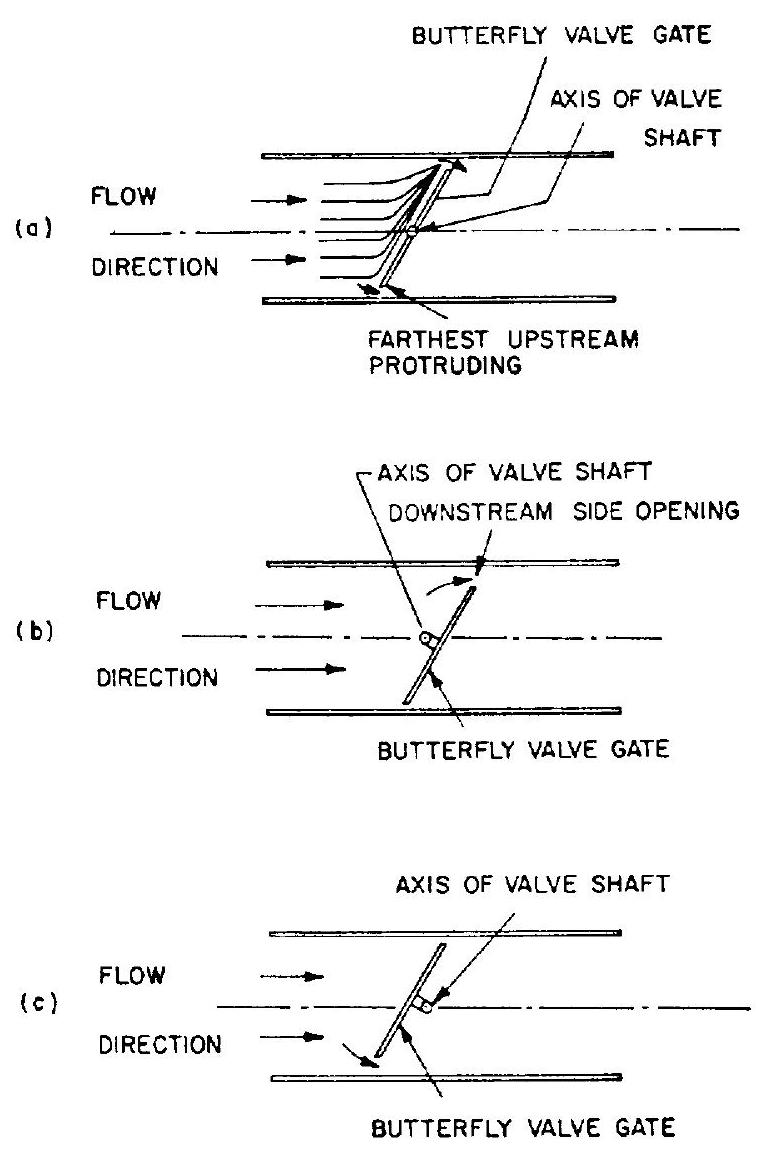 Figure 7-36.-Various locations of valve shaft axis with respect to butterfly valve gate.
The amount of torque required to turn valve shaft and gate is determined by the summation of hydraulic and friction torques. Hydraulic torque is the unbalance of forces on the value gate caused by the flow of fluid around it. If the axis of the valve shaft is located as shown in figure 7-36(a), the fluid striking the gate portion protruding farthest upstream is deflected more than that at a point near the other end of the gate. This produces an unbalanced force which tends to close the gate. Offsetting the valve gate as shown in figure 7-36(b) would further increase the closing torque, because the fluid velocity rises as it approaches the downstream side opening. Consequently, the resulting low-pressure area tends to increase the unbalance in the closing direction. For this reason, butterfly valves are usually designed offset as shown in figure 7-36(c) (also see fig. 7-33). This produces a fluid velocity effect tending to ease opening of the gate, because of the lower net closing hydraulic torque acting on the valve gate.
Nevertheless, the net hydraulic torque will still be acting in the closing direction for most angular gate positions , unless the valve gate is further offset. Friction torque always opposes rotation. For most operational valve designs
where required opening torque, in-lb required closing torque, in-lb friction torque, in-lb hydraulic torque, in-lb (assumed to act in the closing direction) The friction torque varies with the pressure differential across the valve gate, and with the valve gate projected area which is a function of gate angular position. Friction torque can be estimated by
where friction torque coefficient, which is a function of gate angular position (to be determined experimentally) radius of valve shaft at the bearing section, in coefficient of friction between shaft and bearing ( 0.20 for aluminum journal and steel shaft; 0.05 for needle bearing and steel shaft) inside diameter of valve seat lip seal, in pressure differential across the valve gate, psi Hydraulic torque may be estimated by
where hydraulic torque coefficient, which is a function of gate angular position (to be determined experimentally) Figure 7-37 shows plots of required opening and closing torques versus gate angular positions for a typical butterfly valve. In actual design practice, the actuator of a butterfly valve will provide two to three times the maximum
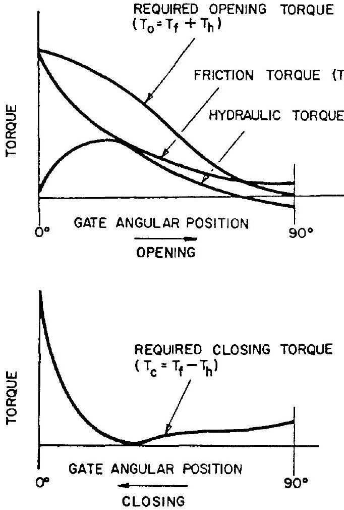 Figure 7-37.-Typical required opening and closing torques versus gate angular position for a butterfly valve.
estimated opening and closing torques. In addition, at the start of the opening stroke, the actuator has to overcome the static friction forces of all seals. Butterfly-type propellant valves are relatively fast acting. Opening and closing times range from 20 to 200 milliseconds.
Sample Calculation (7-3)
The following design and experimental data are given for the main oxidizer valve (butterfly type) of the A-1 stage engine.
Design Data
Radius of valve shaft at bearing section,
Inside diameter of the valve seat lip seal,
Coefficient of friction between shaft and needle bearing, Test Data
| Valve gate angular position, deg | |||
|---|---|---|---|
| 1058 | 0.78 | ||
| 769 | 0.78 | ||
| 87.5 | 1.57 | ||
| 25 | 3.61 |
Determine the required opening and closing torques at the , and angular positions of the valve gate.
Solution
From equation (7-15), the friction torques
From equation (7-16), the hydraulic torques
at
at
From equation (7-13), the required opening torques
From equation (7-14), the required closing torques
Ball-Type Propellant Valves
The major advantage of a ball valve is its low-pressure drop, since it permits in-line, unrestricted fluid flow. Its use also enhances structural soundness for high-pressure service. It has a reliable record in cryogenic and some storable propellant applications, for high-capacity gas generators as well as for lower thrust main chambers (up to about thrust). Up to a nominal diameter of 3 inches, ball valves are comparable to other valve types with respect to space envelope and weight. For larger diameters, ball valves are used only infrequently, because it becomes increasingly difficult to meet flight weight and envelope requirements. However, for ground service applications where weight and size are not critical, the ball valves, in all sizes, are used quite frequently. Many ball-type propellant valves are designed in a mechanically linked, dual-valve arrangement, operated by a single actuator.
Figure 7-38 illustrates the design of such a valve. Here, the valve elements are mechanically linked, controlling both oxidizer and fuel flows. The valves can be sized either individually as shown, and according to the specific volumetric propellant flows, or be designed to have a common size. The sealing of a ball valve is accomplished by lip- or O-ring-type seals, riding on the spherical sealing surface of the valve ball. In our specific case, the valve seal
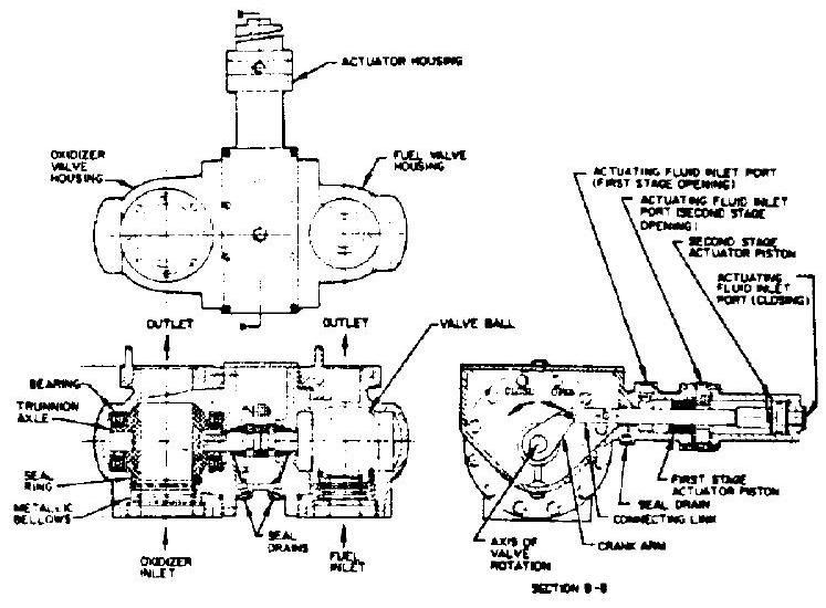 Figure 7-38.-Typical ball-type propellant valve design.
assembly consists of a seal ring and an attached metallic bellows. The area enclosed within the effective seal diameter, , is designed to be less than the effective area of the bellows. During valve closing, this creates an unbalanced force acting on the sealing surface, as affected by the fluid pressure within the bellows.
Each valve ball is trunnion mounted using two integral axles on antifriction bearings. The axis of valve rotation passes through the geometric center of the spherical sealing surface. In most designs, the valve ball rotates from the closed to the fully open position. Typical fluid-flow resistance coefficients for ball-type valves, as determined at the fully open position, are listed in table 7-4. Ball-type valves can readily be used as flow-regulating devices, such as for propellant throttling. Flow characteristics for constant pressure drops of a typical ball valve at various angular positions are presented in figure 7-39.
The activation of the ball valves shown in figure 7-38 is provided by a piston-type actuator, which could be powered by either fuel pressure or inert gas pressure. The reciprocating motion of the actuator is translated to a rotary motion of the balls by means of a connecting link and crank arm arrangement. The opening sequence of the two valves can be adjusted by varying the relative angular positions between the valve axles and the crank arm. The actuator shown has two stages. First, the valves are opened to an intermediate position (partial opening), then to the
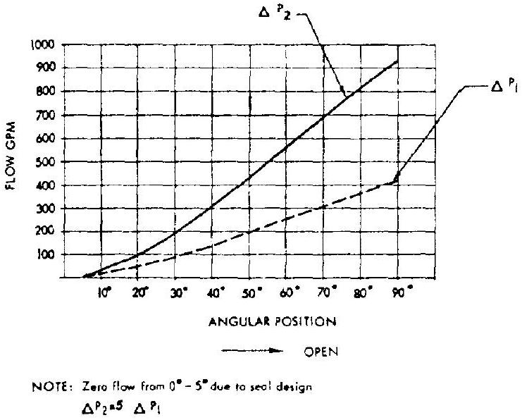 Figure 7-39.-Flow characteristics for constant pressure drops of a typical ball-type valve at various angular positions.
fully open position using separate pistons for each stage. The closing of the valve is effected by venting both opening ports and pressurizing the closing port. Dual seals with a drain between them are provided for all dynamic seals sealing to ambient.
Poppet-Type Propellant Valves
Figure 7-30 shows a typical poppet valve with metal-to-metal seats. This valve is designed to be pneumatically operated and normally closed. All sealings are achieved without the use of elastomers. Because of the nonwiping characteristics of all dynamic seals, this design is particularly suitable for use with fluorine and other highly reactive propellants. A main advantage of poppet valves is their relative simplicity. This is largely due to the reciprocating operation which permits the direct, in-line connection of an actuator. However, this arrangement requires turning of the flow inside the passage, and consequently results in relatively high-pressure drops. Typical fluid-flow resistance coefficients for poppet valves are given in table 7-4.
Figure 7-40 presents the design of a typical, large size ( 6 to 10 inches nominal diameter), poppet-type propellant valve. To reduce the unbalanced hydrodynamic forces, and thus the size of the actuator, a balance chamber is provided. The effective area and the fluid pressure
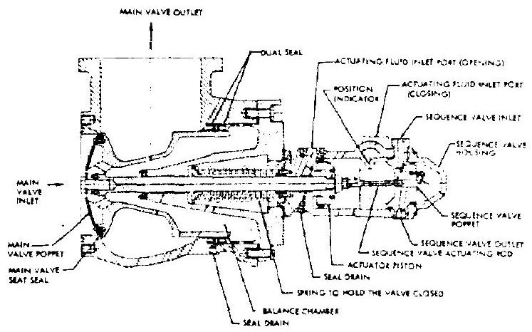 Figure 7-40.-Typical large-size poppet-type propellant valve design.
in the balance chamber are dimensioned so as to result in the proper counteracting force which varies as a function of the unbalanced force at various positions of the valve. A small sequence valve is mechanically attached to the main valve. This type of poppet valve is suitable for highflow and high-pressure, storable as well as cryogenic, propellant services.
Venturi-Type Propellant Valves
Figure 7-41 presents a typical design for a venturi-type propellant valve. In certain installations, it may be desirable, for various reasons, to use a valve of a nominal size smaller than that of the main duct. A valve installed in the throat of a venturi is a possible solution. The smooth contours of the venturi limit pressure drop penalties to a few psi. Adjacent ducting permitting, it is conceivable that the venturi may simultaneously be used for flow measurements. Typical resistance coefficients for venturi valves are given in table 7-4.
The venturi may be designed to operate as a cavitating venturi. Based on Bernoulli's energy equation (eq. (7-2)), the minimum pressure of a liquid is made to fall below its vapor pressure. As a result, a gaseous region forms at the throat. If this gas moves through the throat at the velocity of sound, downstream pressure variations and disturbances cannot advance beyond the throat. Up to minimum pressure differentials across the venturi (say 20 percent of upstream pressure), flow rate is dependent on upstream pressure only. When used as a throttling device, the cavitating venturi affords smaller pressure drops,
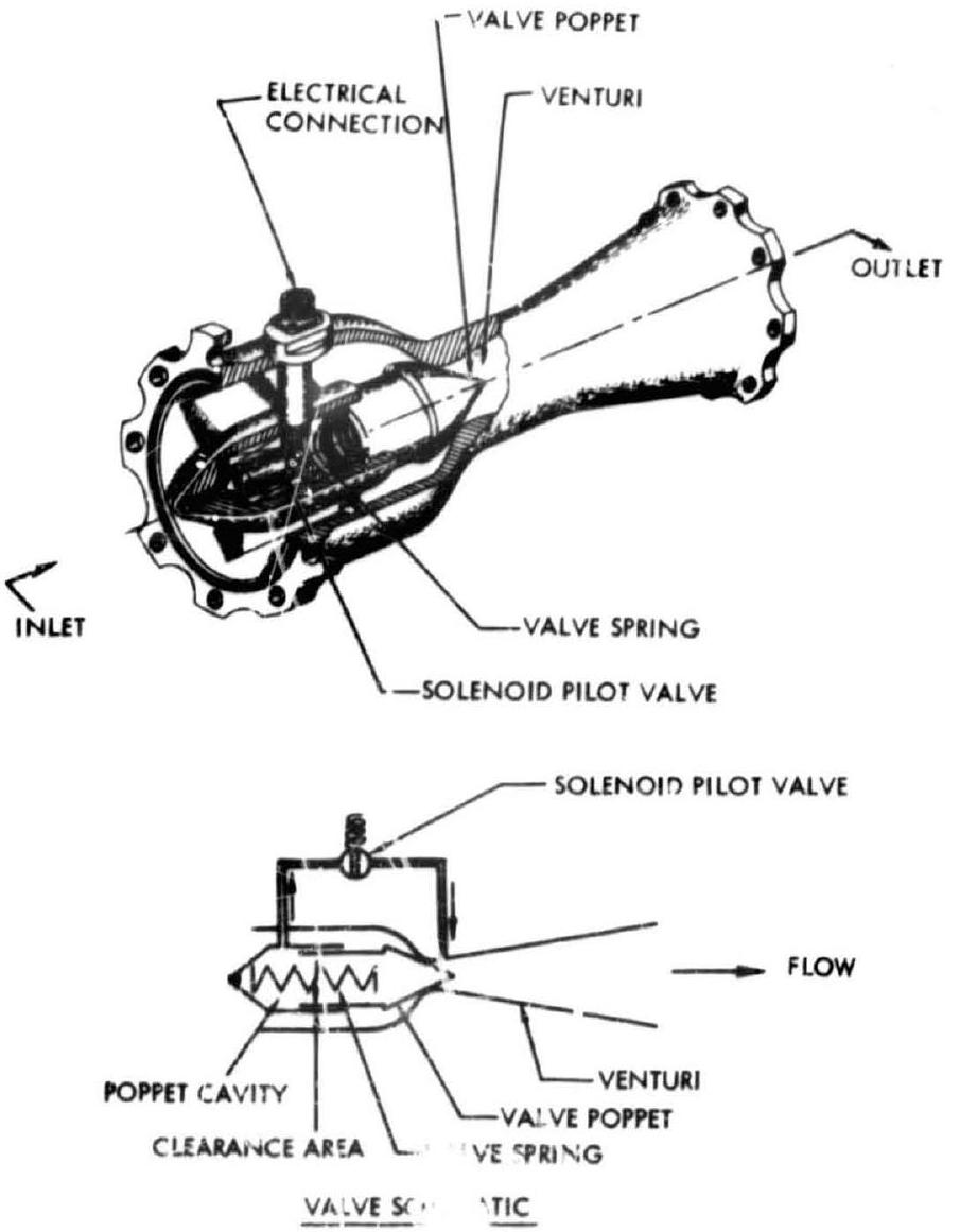 Figure 7-41.-Typical venturi-type propellant valve c'esigned and manufactured by Fox Valve Development Co.
since the gaseous characteristics at the throat effect a near linear relationship between flow rate and supply pressure, rather than according to a square law. The fluid-flow venturi valves have been applied successfully in cryogenic and storable propellant services.
In fluid-flow systems which require flow limitation as well as a shutoff control valve, the venturi valve with a cavitating diffuser will provide both, at a weight of only the valve and at a pressure drop of only the venturi.
Venturi valves occupy a relatively long space in the direction of flow, between 4 to 6 times of the line nominal diameter. This length imposes limitations on size and application in engine systems. However, venturi valves up to 10 inches nominal/diameter have been successfully built for rocket vehicle systems.
Figure 7-41 presents a typical verturi-type propellant valve designed and manufactured by Fox Valve Development Co . It is a pilot-operated shutoff valve which consists of a convergentdivergent venturi section with a simple, spring- loaded poppet seated at the throat. Propellant line pressure controlled by a solenoid pilot valve is used to actuate the valve open or closed. As shown in the valve schematic (fig. 7-41), the normally closed pilot valve is inserted in a passageway interconnecting the poppet cavity and an opening in venturi throat. Normally, upstream propellant pressure fills the poppet cavity and provides additional seating force on the poppet in the same direction as the valve spring to assure valve closure. When the pilot valve is energized to open, propellant pressure behind the valve poppet is vented out at a greater rate than it can be replaced by leakage through the poppet clearance area. This results in a reduced pressure overcon.ing the valve spring and causes the main valve poppet to open. The venturi valve contains no dynamic seals. Since the valve body is not pierced by a shaft or actuator rod and there are no dynamic seals, no pathways exist for leakage to ambient. The small number of moving parts further enhances reliability.
Gate-Type Propeliant Valves
Figure 7-42 shows a typical design of a propellant gate valve. Its major advantage is unrestricted fluid flow, resulting in low-pressure drop. It also provides a relatively short distance between the valve inlet and outlet in the direction of the flow. The design shown in figure 7-42 uses elastomer O-rings as the valve-seat
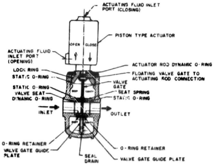 Figure 7-42.-Typical gate-type propellant valve design.
seal. These are suitable only for mediumtemperature services. In cryogenic application other seal types are required. Gate valves are designed for propellant line pressures up to 3000 psi . Because of their relative bulkiness, gate valves are limited to low propellant-flow applications such as for gas generator control and ground-support services.
Needle-Type Propellant Valves
A typical needle-type propellant valve is shown in figure 7-43. This valve type is used for extremely low flow applications such as for attitude-control thrust chambers. The assembly shown is a dual-vaive arrangement, positively linked by a mechanical yoke. The valve body is an integral part of the thrust chamber injector assembly. Both valves are normally closed. Their actuation is provided by a quick-response electric solenoid.
Sealing at the valve seat is achieved by the elastomer tip of the valve needle. Dynamic sealing at the actuator rods is achieved by means of metallic bellows. This seal design is compatible with cryogenic as well as storable propellants. The pintle vanes provide a guide for the reciprocating motion of the valve needle.
In chapter XI we will discuss other special varve types, as they are needed for very low propellant flow service in miniature-size space engines.